|
Goal: To see if there is a correlation between the protrusion parameters matrix and the math of the cells using linear regression. Training matrices: DMSO treated cells (in order): cell 14, cell 15, cell 12, cell 10 CK666 treated cells (in order): cell 43 ,cell 48 , cell 55 , cell 53 variables: Count, largest protusion volume, total protustion volume, protrusion fraction, largest protrusion length, largest protrusion angle, and total protrusion angle. Experiment 1Dependent value (y): derivative using savitzky-golay variables:
To get rid of rows without Y values training.set.complete<-training.set[complete.cases(training.set),] I did this because the smoothing window on the sg filter leaves a lot of blank values for the derivative. Results: all the parameters were significant except largest protrusion angle, and total angles. The largest protrusion length is only significant for the first few fits. 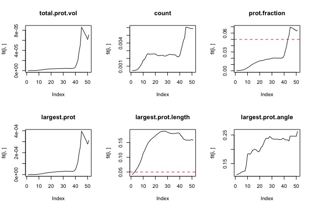 Experiment 2Dependent value (y): curve method variables:
Experiment 3Dependent value (y): bi-modal with cutoff (ie, is the cell turning or not turning?)
Results:
 To do next:
add more cells to the training set write function to find average turning point prediction
0 Comments
Goal: Add Bootstrap to the cell line catalog page.
Here's what I have learned so far:
Use Bootstrap default settings and do any additional formatting using your own CSS files:<!-- Latest compiled and minified CSS --> <link rel="stylesheet" href="https://maxcdn.bootstrapcdn.com/bootstrap/3.3.7/css/bootstrap.min.css" integrity="sha384-BVYiiSIFeK1dGmJRAkycuHAHRg32OmUcww7on3RYdg4Va+PmSTsz/K68vbdEjh4u" crossorigin="anonymous"> <!-- Optional theme --> <link rel="stylesheet" href="https://maxcdn.bootstrapcdn.com/bootstrap/3.3.7/css/bootstrap-theme.min.css" integrity="sha384-rHyoN1iRsVXV4nD0JutlnGaslCJuC7uwjduW9SVrLvRYooPp2bWYgmgJQIXwl/Sp" crossorigin="anonymous"> <!-- Latest compiled and minified JavaScript --> <script src="https://maxcdn.bootstrapcdn.com/bootstrap/3.3.7/js/bootstrap.min.js" integrity="sha384-Tc5IQib027qvyjSMfHjOMaLkfuWVxZxUPnCJA7l2mCWNIpG9mGCD8wGNIcPD7Txa" crossorigin="anonymous"></script>
This is super simple, straight from http://getbootstrap.com/getting-started/ . Just add these links and script file to your index.html the same way any other style sheet and you have access to all of the bootstrap default settings. Similarly you can download the compiled Bootstrap files and include them that way.
Use Bootstrap to create a theme:
I hadn't used Less before, but I was able to start playing around with the setup. Bootstrap uses Less variables to set up a theme. In order to edit them you need to be able to compile the new .css code.
I mostly followed the steps on this website, although I had to make a few changes since this is 2 years old.
Demo of slider with the figure width set to 100% instead of 500%
With the actual slider you only see the middle image along with a bit of the incoming and outgoing images.
  
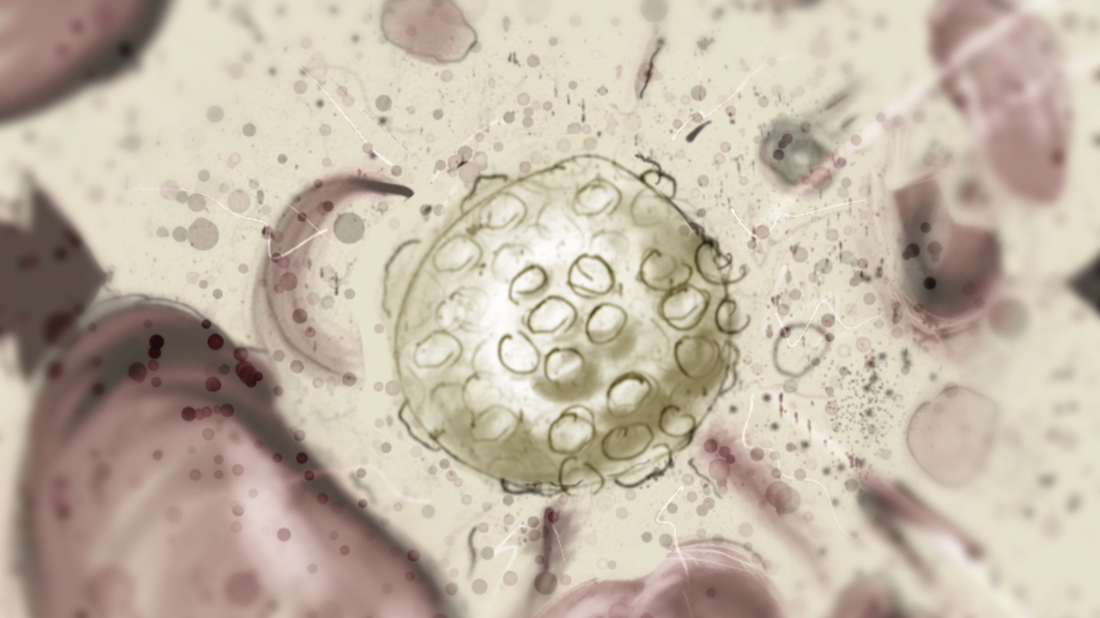
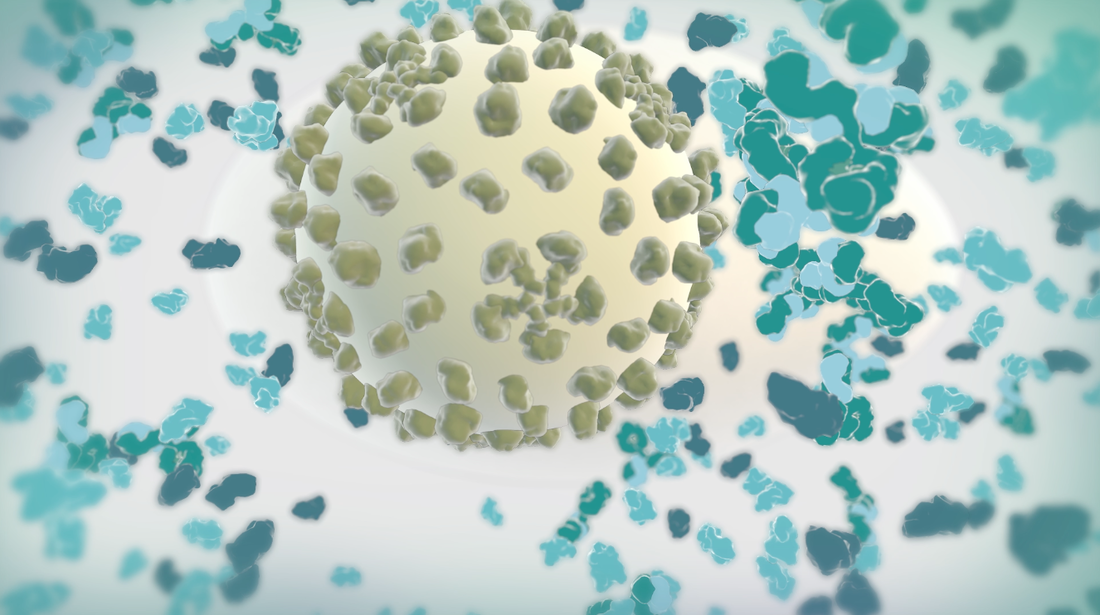
Goal: To replace 2D footage with 3D animation in opening sequence of animation about the hepatitis B cycle. In the opening sequence of this animation the camera follows the virion as it approaches a liver cell. I want it to feel frenetic, and to have many proteins fly past the screen as we move forward.
Set up: I used proteins from the cellPack model of blood serum, although not at the exact relative concentrations. The proteins are mostly IgG and Albumin. 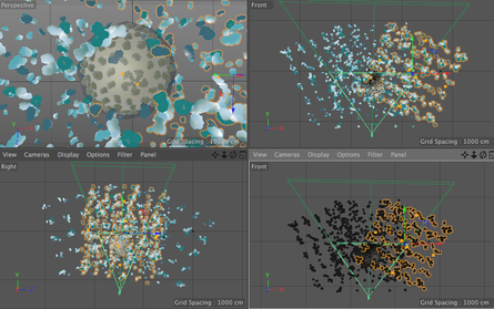 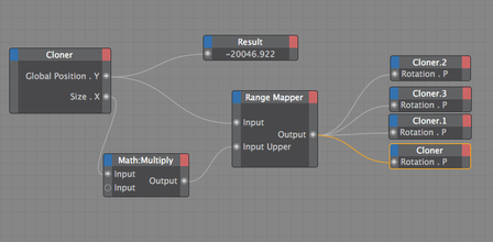 This set up involves 4 cloners spinning towards the camera surrounding the virion to reduce the number of proteins in the scene. Their rotation is dependent on their position. I used the size of the cloner to calculate the rate at which they should spin.
The virion is surrounded by a low poly sphere with a simulation tag on it and two of the cloners have simulation tags on them. A challenge was to get the virion to move randomly through the scene but to end up in the location I needed it to be for the cross fade to the diagram image. I ended up applying a turbulence field to the virus and having the simulation tag turn off once it arrives as the docking site. I couldn't use a random effector because it would also move all the surface proteins. Vibration tags gave me issues with permanently changing the location of the particle. I was able to render the scene at about 10 secs per frame with no ambient occlusion and no shadows. I used a depth pass and created the depth of field effect in After Effects.
The goal of this set of experiments was to be able to control the position or movement of a single clone within a MoGraph Cloner. The system I had in mind when I started these tests was a ligand binding to a substrate, but it could be applied to many different systems.
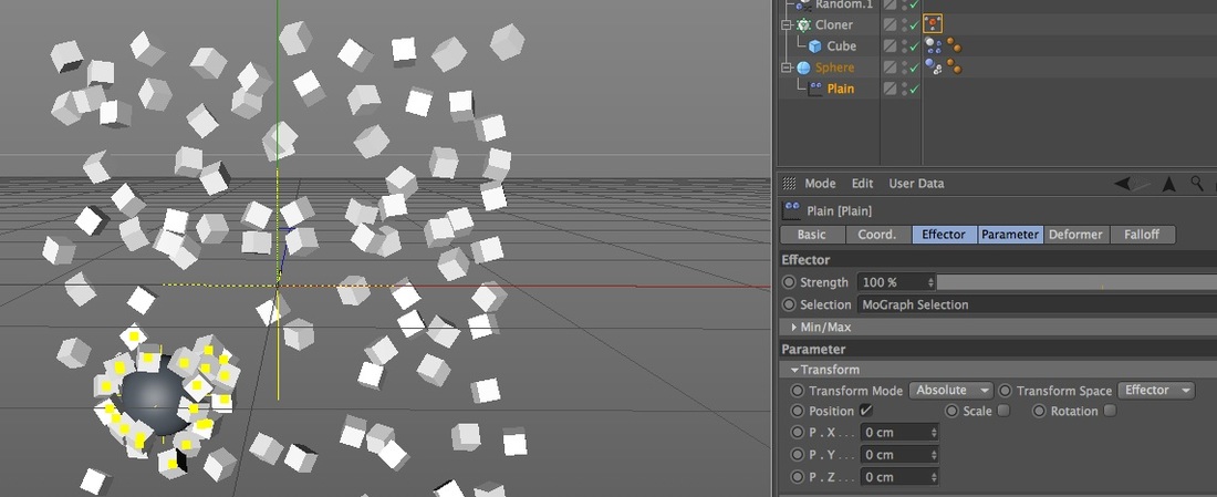
1. Attractor Field with Random Effectors The attractor field gets a lot of the work done, and for many cases, this set up is all you need. I have simulation tags on both the clones and the sphere, and an attractor field with a falloff as a child of the sphere.
To achieve the movement I have in this video, I created two Random Effectors, one with small displacement and one with very large displacement. The problem with the Random Effector is that each clone is never going to be able to truly change it's position (to my knowledge). It's not as obvious in the example above, but when you color the clones, you can see they never mix.
2. Plain Effector and a MoGraph Selection Tag (still with Random Effectors) In this next example I used xpresso to conditionally add clones to a MoGraph Selection tag based on their distance from the Sphere, and then used a Plain Effector to change their position. In this case I targeted their position to the Sphere, but what separates this from the Attractor field example is I can use the Plain Effector to change location in just one direction, like 50cm in the x, instead of all being attracted to the same point.
Here's the important aspects of this setup:
Here is my xpresso setup.
You could of done this with just a Python node but I thought this was visually more comprehensible. 
The downside of this setup is it still lacks a true random walk, and I still can't explicitly control a clones position independent of all the other clones, whatever I set the Plain Effectors Transform parameters to their going to be applied to all the clones in that selection. Enter the Dynamic Body State Node (!).
3. Dynamic Body State Node It drove me nuts that the MoGraph Data node didn't have position as an input port option, but I discovered the Dynamic Body state Node does, and so much more. The "Object" for the input port is the object that has the dynamic tag on it (Dynamics must be turn on), so in my case it was the cloner. The first version I did of this I just tried to recreate the setup I have in the previous examples. You can use the Dynamic Body State node to change the position of a clone, but if you do, it overrides the collision calculation, so your clones will end up intersecting. So I used the "Add Force" and the "Linear Velocity" inputs. I did two different versions, the first one the random walk vector decreases as the cubes get close to the sphere, so they can't come back off the sphere very easily.
def main(): global randwalk global field spherev=spherepos-clonepos if (frame+index)%5==0: #so that every clone does not change direction every frame newclonepos=randvector*steplength else: newclonepos=currwalk if dis< mindis: pos=dis else: pos=mindis randwalk=newclonepos#*pos/mindis #2nd term reduces their chance of escaping field=spherev*(-pos/mindis+1) #linear falloff You can download the file to make this video:
Nested Iteration
I then set up a nested iteration so that I could add any number of clones of spheres as well. This enables you to change the number of either clone on the fly and the setup still calculated the attraction appropriately, as you can see in the video below.
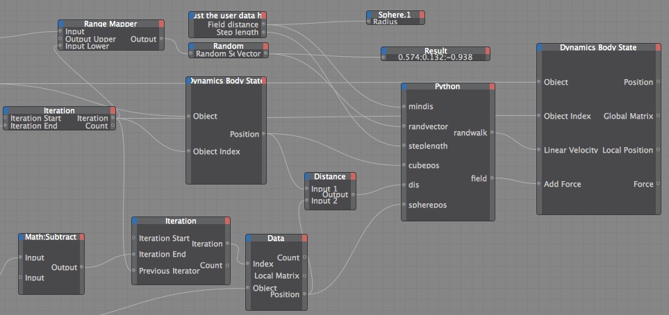
I experimented a lot with the different input ports for the Dynamic Body State node, and this setup works well, but if you watch the upper right sphere in the video it seems to attract the cubes more strongly. I've tried rotating the clones and changing the count, so I'm pretty certain it has to do with the Object Index, which makes me think the iteration isn't working exactly how I expect, I would love any insight on that. I also think there is a more elegant way to get a random vector, I just initially saw some bias in the simulation when I had the Iteration going direction into the Random Seed, and it's my understanding that sequential random seeds have similar random tables, so I used a noise node to get a different Random Seed.
Hope you enjoy!
Here I used ePMV and MoGraph cloners, and Inheritance effectors to make a vesicle fuse with a bilayer. I outline how I did it in this tutorial.
|
Categories
All
|
||||||||||||||||||||||||
 RSS Feed